The layout was drawn with CorelDraw. By clicking on the image you get an PDF file, which can be zoomed in. The elements are organized in layers, which can be switched on and off to get a better overview.
The layout is inspired by the Vox AC30 HW From 2010.
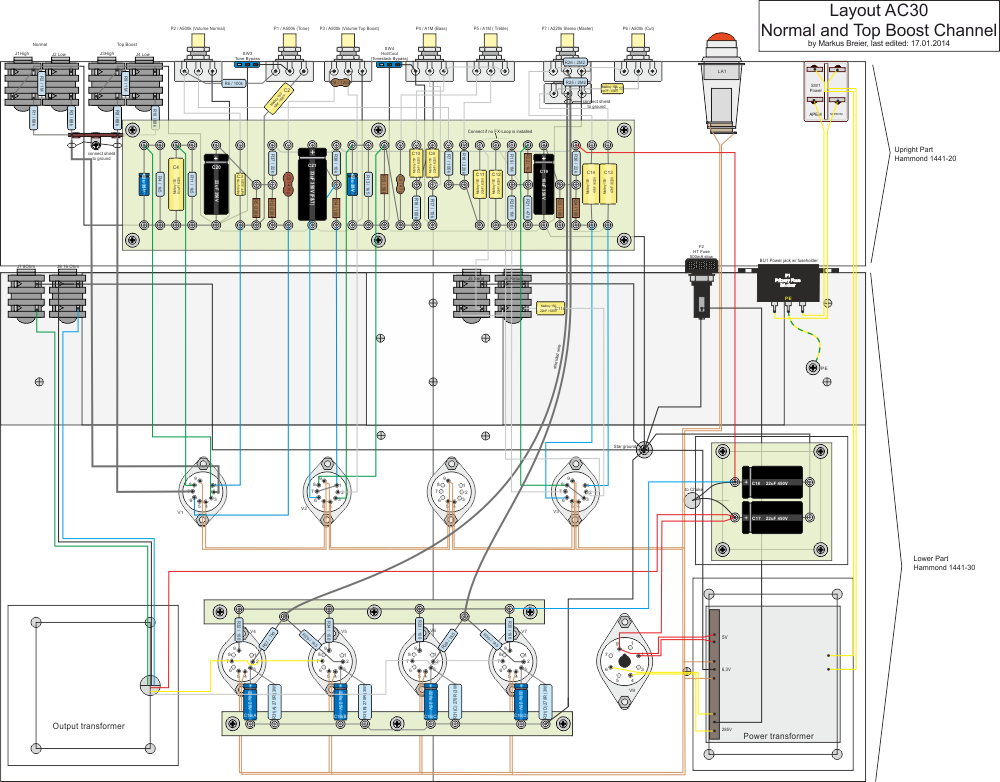
The heater wire has to be twisted tightly to reduce hum. The color of the leads of the output transformer depict the colors of my OT. The Rings on the shielded wire between the Master pot and the power tubes are the ground connections of the wire shield. The shield is connected to ground only at the pots and is insulated with shrink tube on the other end.
The layout assumes a power transformer with a center tap at the 6.3V terminal. If your PT doesn’t have a center tap, then you will have to add a virtual center tap using two 100 ohm resistors.
Contrary to the schematic, the power tubes each have their own resistor and capacitor. Their values have been changed accordingly. (Each resistor has 270Ω, if one single resistor is installed, its value should be 68Ω)
At the moment, the layout contains just a passive FX loop. The empty tube socket is included to have the possibility to add an active FX loop later.