The boards, on which a large part of the passive elements is mounted, are eyelet boards. They could also be made as turret boards or tag boards
I used 2mm GRP (glass reinforced plastic) and 1/8″ eyelets
The boards are cut and drilled according to the layout drawing and the eyelets were punched in.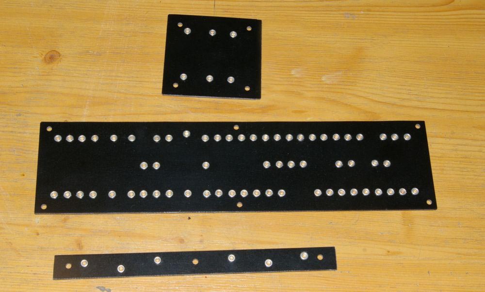
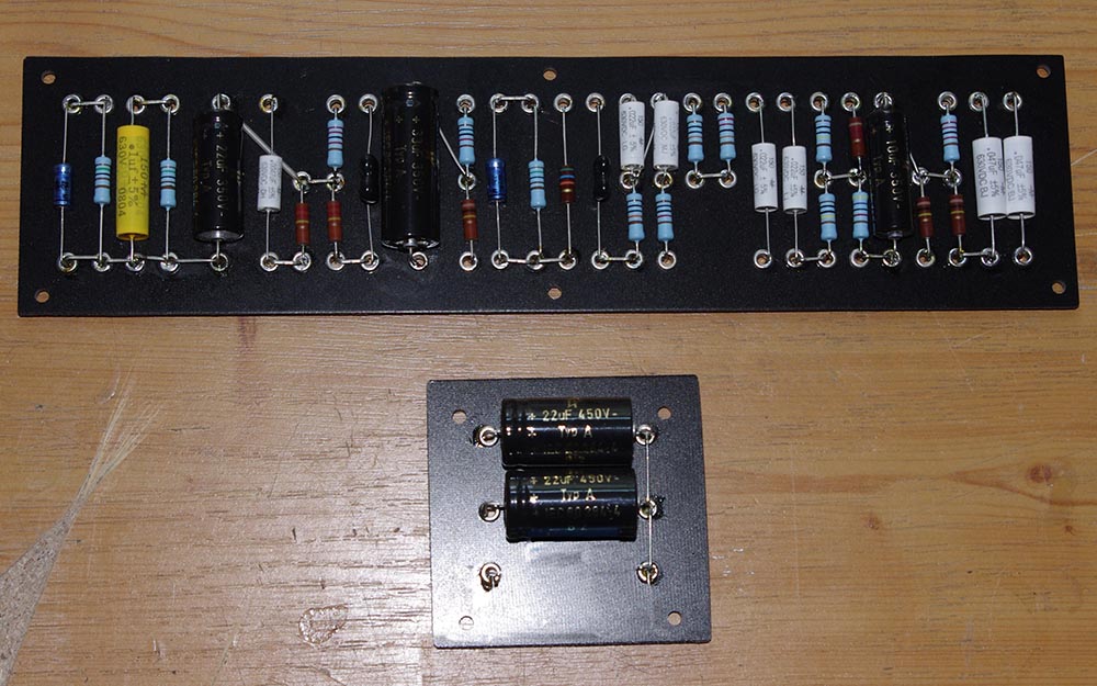
Once all the eyelets are in, the electric parts can be soldered to the board. In the picture the different resistors can be discerned. The blue ones are 1W metal film resistors, the brown ones are the carbon compositum resistors. The unused eyelets on the board with the electrolytics are from the planning stage, when it was planned to place R31 and C16 on this board. This was changed later. The wire between C20 and R5 is insulated with silicon tubing.
Check if all wire bridges are present!
If radial electrolytics are used instead of axial ones, they have to be fastened with cable ties or adhesive because of their wight.
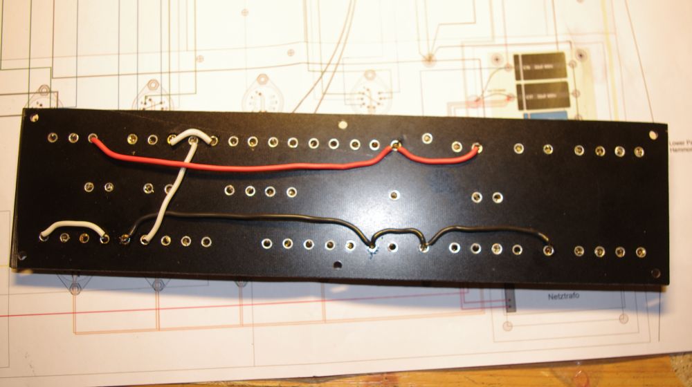
When the front side is done, the connections on the rear are made from wire. The first step are the interconnections on the board.
After that, the ground connections (black), connections to the tube sockets (green, blue, white) as well as the connection to the power supply (red) are attached to the board.
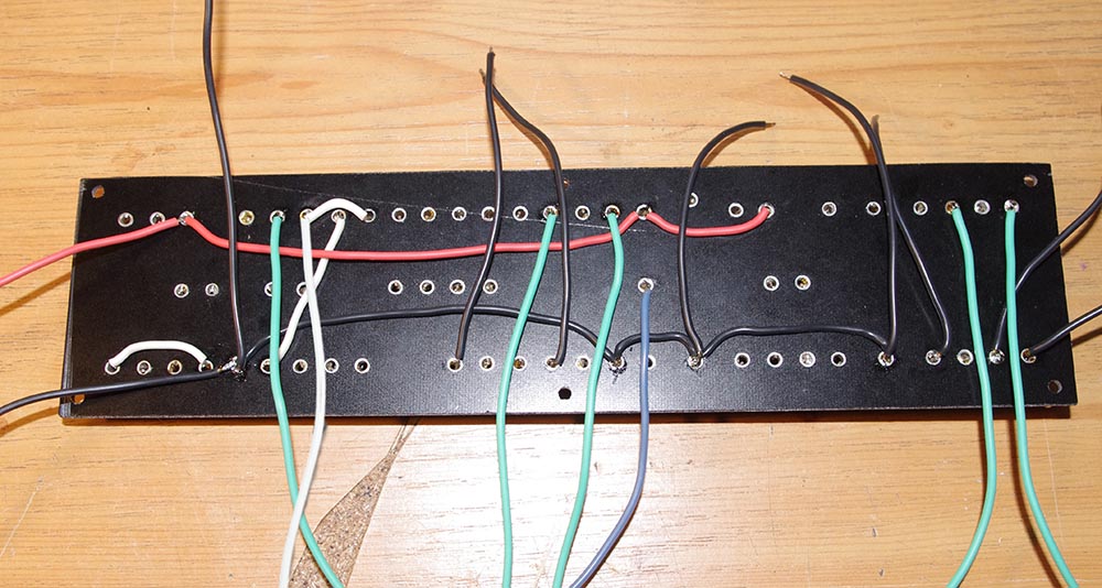
After checking all solder points, the boards can be mounted to the chassis.