On some of the pictures the standby switch can be seen. Because of possible issues in conjunction with a GZ34 rectifier, the standby switch was removed from the circuit. The AC30 doesn’t need it anyhow.
Heater wiring
The first step is the routing of the heater wires. These wires should be twisted tightly and carefully to prevent noise. Hum pickup will be cancelled because of the twisted wires. However, this only works, if the two wires are twisted consistantly. To achieve this, I used a cordless screwdriver, twisting the wires before cutting them to length.
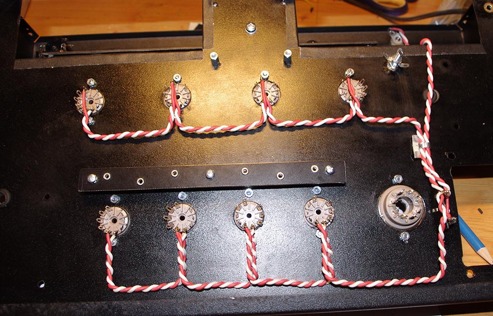
At the pre-amp tubes, pins 4 and 5 are connected. The pictured wiring allows the twists to reach to the socket.
As the transformers are heavy, I wired everything else first and mounted the tranformers as late as possible. This way, the chassis can be handeled more easily during the construdtion.
Input Jacks
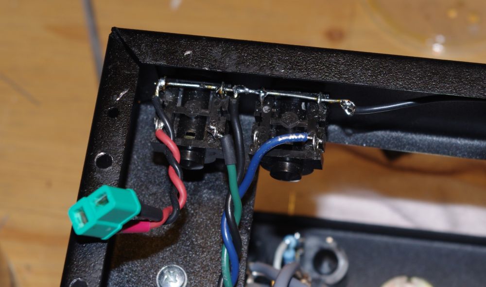
Next I wired the input jacks. Each channel has one pair. Pictured here is one pair, the high input on the left, the low input on the right.
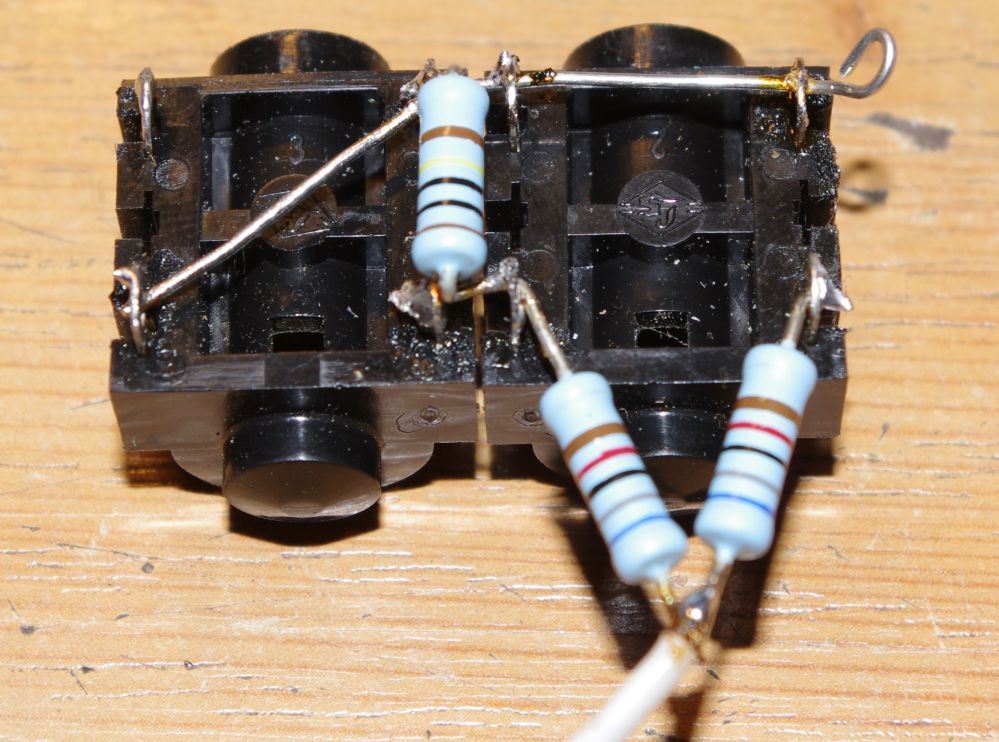
Here are the pairs mounted to the chassis. The leads to the first tube are made with shielded wire, because any noise picked up at this stage is amplified strongly. In the picture the screen of the shielded wire is connected with an additional wire to ground. However, it is already grounded by the solder terminal, which is connected to the chassis, therefore I got a ground loop. So I removed the ground wire. Another option would be to isolate the solder terminal.
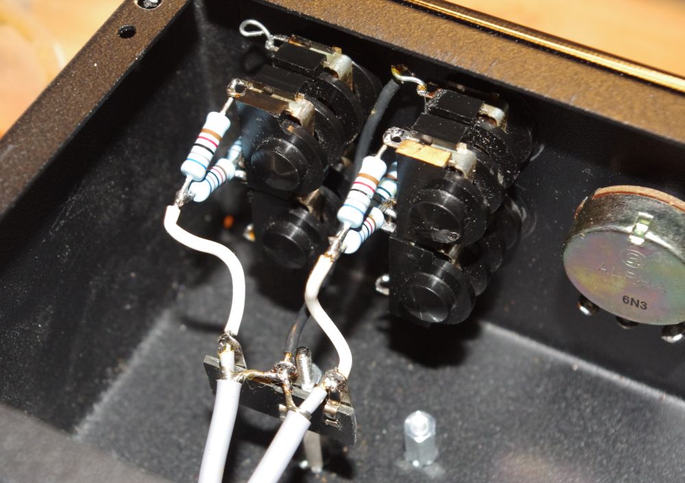
At the tube end of the shielded wire, the screen is not connected, but isolated with shrink tube.
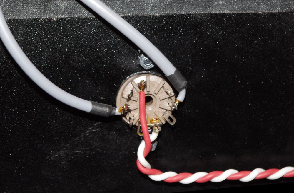
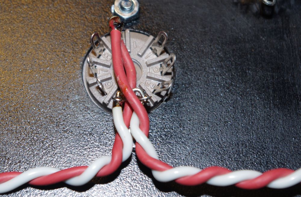
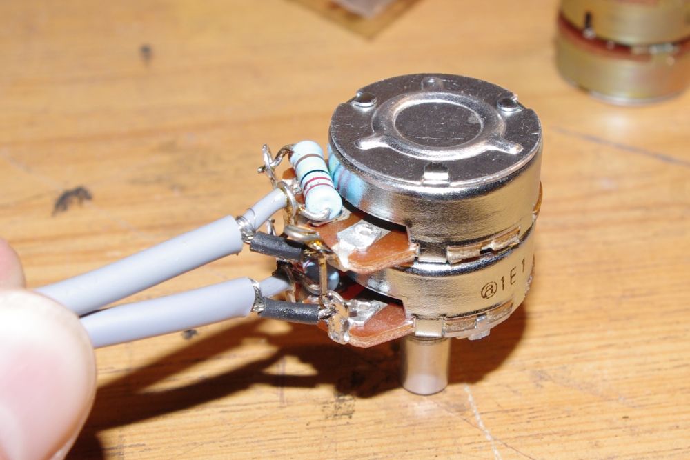
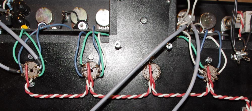
Mastervolume
It is a little tight around the pot of the master volume, therefore I wired it outside the chassis, together with the cut pot and mounted them as a unit. Here again shielded wire was used, with the screen connected to ground at the pot. The two 2M2 resistors R25 and R26 are soldered directly to the pot.
Be careful, on the pictures below R25 and R26 are connected wrong. They should be connected between the middle terminal and ground.
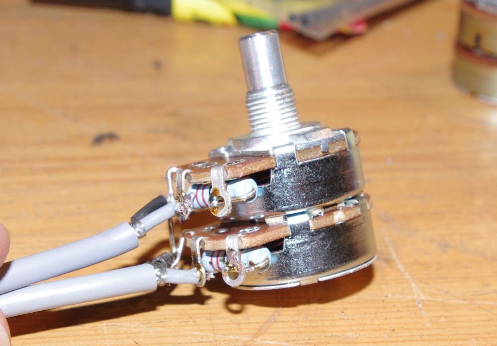
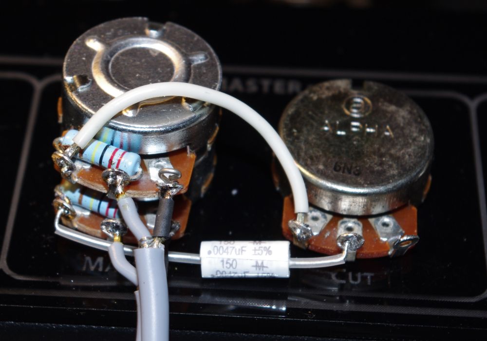
The connected cut control:
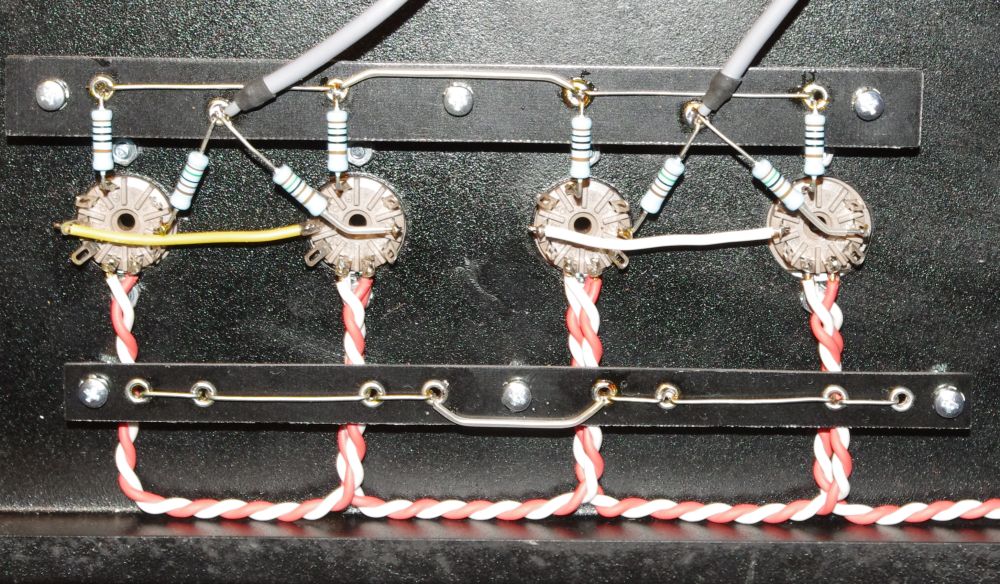
Insert Board
Now the board can be inserted and wired. Here are the controls of the channels:
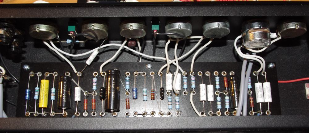
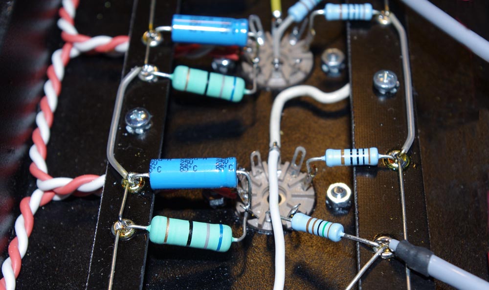
The red wire on the right side connects to the board with the electrolytic capacitors. Now the tube sockets of the pre-amp and the phase inverter are connected:
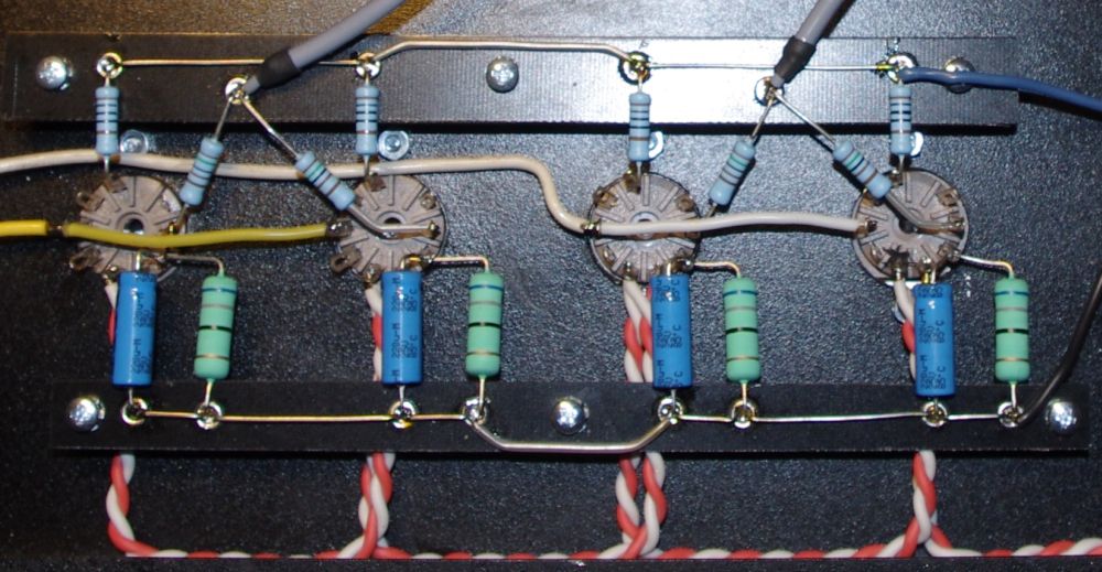
Power Tubes
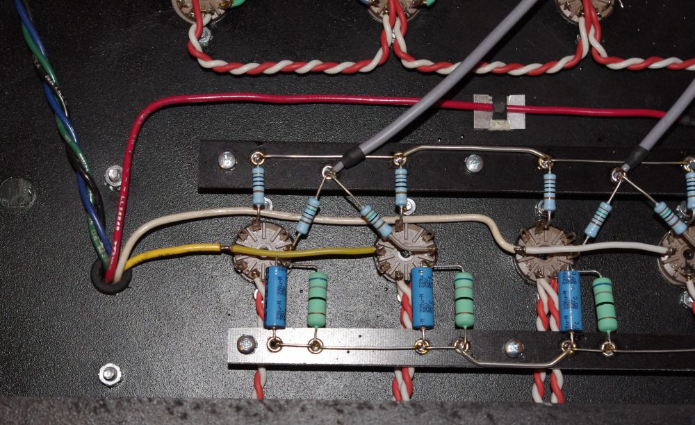
The next step was the wiring of the power tubes. The leads of the resistors are insulated with silicon tubing in areas where there is danger of a short circuit.
As already mentioned at the layout page, I use separate resistors and capacitors for the cathodes of the power tubes. Originally, there is only one common resistor and one common capacitor for all four power tubes. However, these common parts put the tubes under a lot of strain. By using separate R/Cs, the strain is reduced and the tubes should last longer. However, the values of the separate resistors have to be different from the common one. The common one has a value of 68 Ohms, the separate ones 270 Ohms.
(The Original AC30 uses a 50 Ohms resistor, which is very hard on the tubes.)
There should be a little distance between resistors and electrolytic capacitors. The resistors should also be a little higher up than the electrolytic capacitors.
This is because the resistors get quite hot, which isn’t good for the electrolytic capacitors. They can dry out and can have a malfunction. The distance does help. In addition to the distance, consider that hot air rises, so when the capacitors are lower, they are not directly bypassed by the hot air.
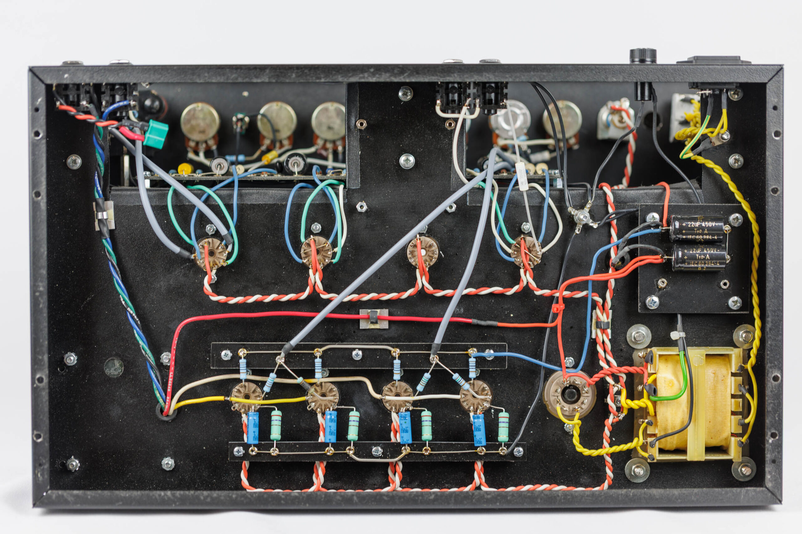
Transformers, Rectifier and Power Supply
Now it is time to mound the transformers and the choke, because now only the wiring of the transformers, the rectifier and the power supply is missing.
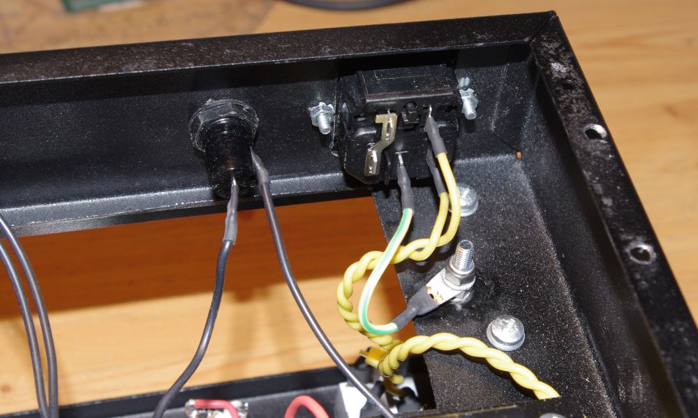
The power jack and fuse holder for the secondary voltage are wired. The protective ground is mounted with a separate screw, contact washer and locking nut. Beneath the shrink tube on the picture, the wire is wrapped around the solder tag before soldering. That way it endures hard mechanical stress.
The rectifier is connected to the power transformer with twisted wire.
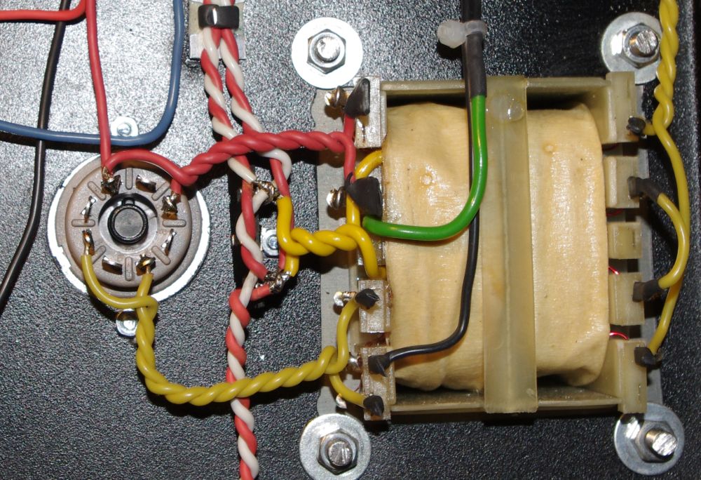
The thick yellow wires in the middle of the picture are connected directly to the transformer and are connected to the heater winding. The thick green wire is the center tap of the heater winding and is connected to ground. If you don’t have a center tap, you have to create a “virtual” center tap by connecting the heater wires with two 100 Ohm resistors to ground.
The yellow wires on the right side of the picture are the primary connections of the power transformer and are connected to the power switch.
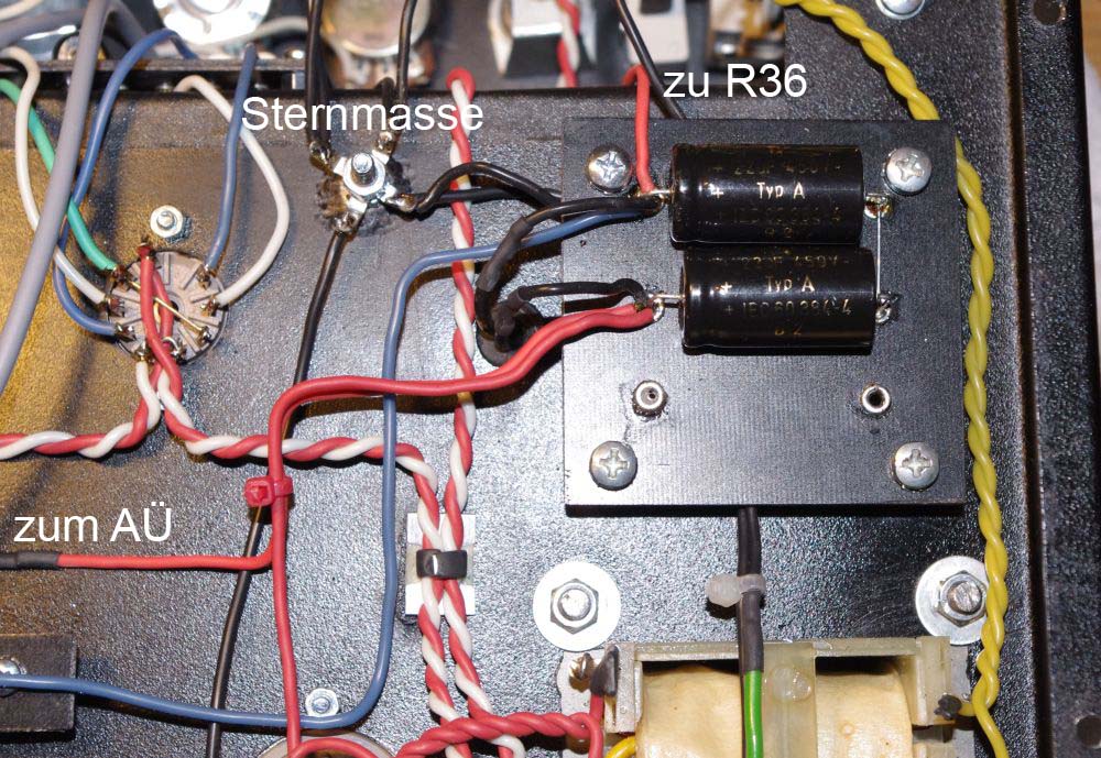
Here you can see the board with the electrolytic capacitors and the remaining connections of the power supply.
(Sternmasse = star ground, zum AÜ = to output transformer, zu R36 = to R36)
The output transformer is connected as well.
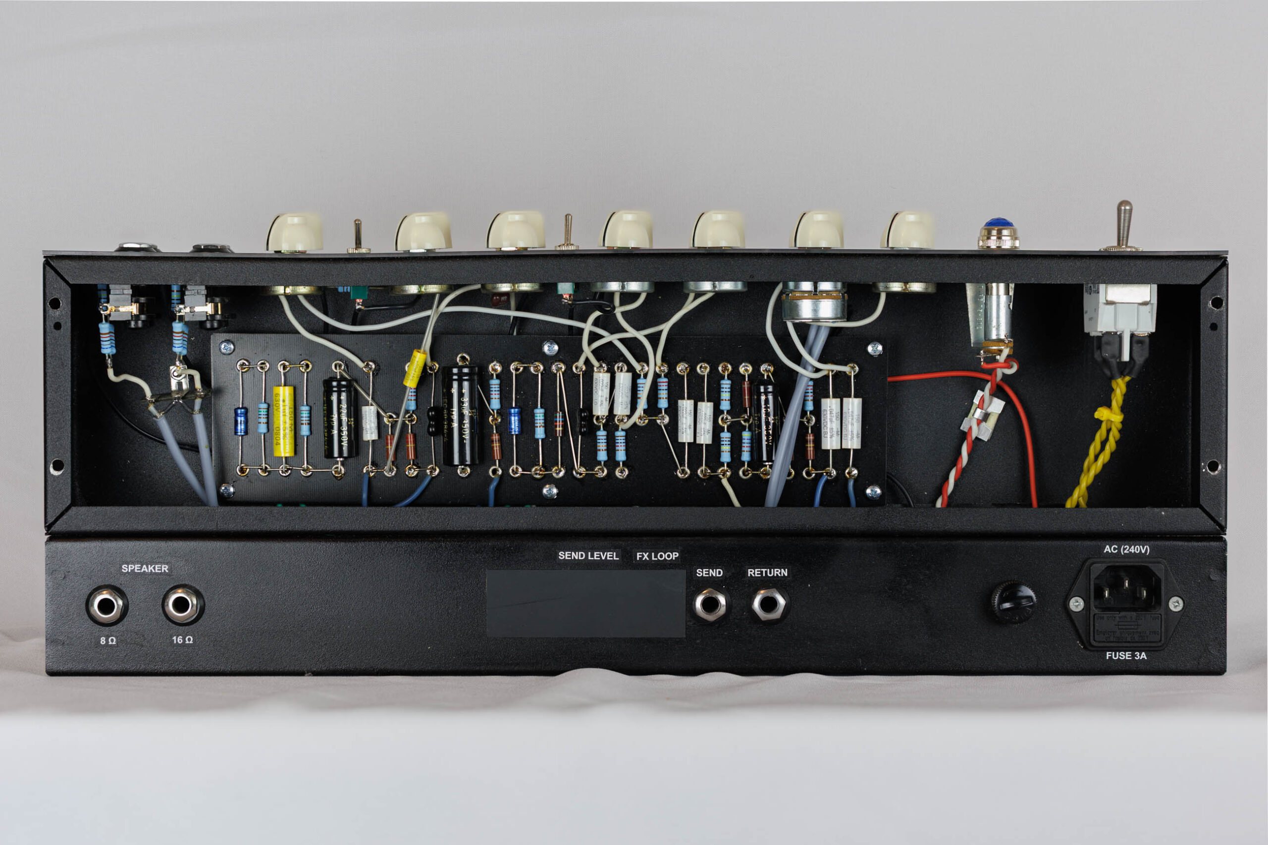
Here are the speaker jacks. The output transformer pictured has connections for 8 and 16 Ohm speakers. The green T-connector connects the 8 Ohm output with a jack in the mounting board. The internal speaker of my cab is connected with this jack. If an external speaker is connected, the internal jack will be disconnected.
The used T-connector is very tight and provides good contact.
Here is how it looks finished:
And the backside:
Now the tubes can be plugged in and the voltages should be checked. If everything is ok, you can test the amplifier. Remeber to never use the amp without any load at the output!
If your amp works, plug in your guitar and rock on!
Have a lot of fun with your AC30!
All that is missing now is a cab.